# Development information

# Communication with the P1 port of the Fluvius Smart Meter
All data communication with the Fluvius Digital Meter runs via the P1 port. The P1 port follows the DSMR 5 standard of the Dutch Smart Meter, extended with the e-Mucs specification.
S1 Port
The Fluvius digital meter also has an S1 port. This user port (S1) is designed to provide "raw" data to an application (CEMS) at a particularly high frequency. The application must further process this "raw" data to make advanced calculations allowing for very detailed consumption feedback and control.
# Physical connection
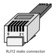
The P1 port is a serial interface that uses a standard RJ12 connector.
RJ11 vs RJ12
The only difference between RJ11 and RJ12 is in how they are wired and the number of the wires that are being used. RJ12 is a 6P6C wiring standard. RJ11 is a 6P4C wiring standard and only has four wires connected and the remaining two slots are no longer used.
For the CDEM device it does not matter if you use an RJ11 or RJ12 cable because the power supply of the meter is not used (two outer pins). The reason being that the current the meter can deliver at this port is quitte limited (less than 300mA).
| Pin | Signal name |
|---|---|
| 1 | + 5V (Power supply) |
| 2 | Data request |
| 3 | Data GND (ground) |
| 4 | Not connected |
| 5 | Data |
| 6 | GND (ground) |
Safety
In order to protect both the user and the Fluvius digital meter, the P1 port is galvanically isolated from the mains.
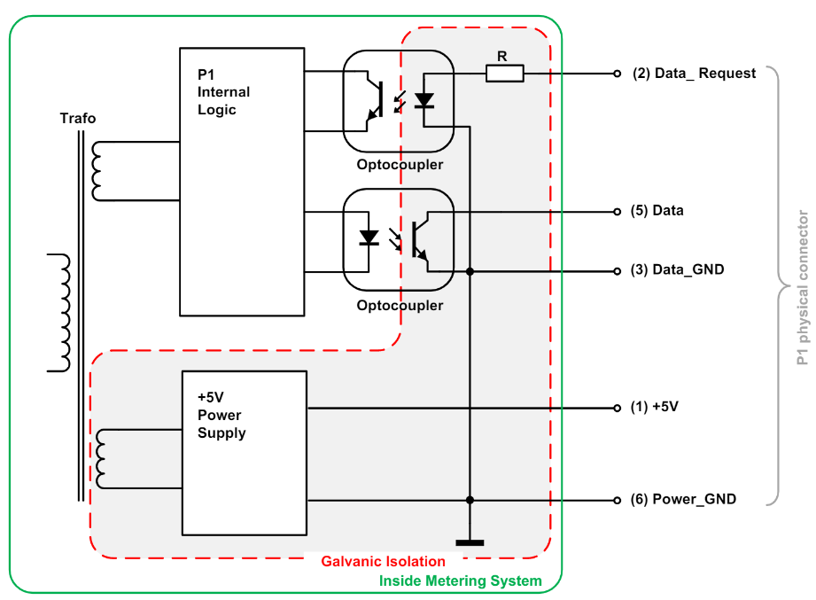
# Power supply
The P1 interface provides a stable +5V DC power supply via pin 1 (5V) and pin 6 (GND) to provide a connected IoT device with a power source.
U = 5,0 V ( max = 5,5 V with I = 0 mA , min = 4,9 V with I = 250 mA )
# Data request
The P1 port is activated (will start sending data) by setting "Data request" (pin 2) high (4,0V to 5,5V). While receiving data, this line must be kept high.
Warning
To stop receiving data the "Data request" line must be put in a high impedance mode and must not be connected to the GND or 0V
# Data
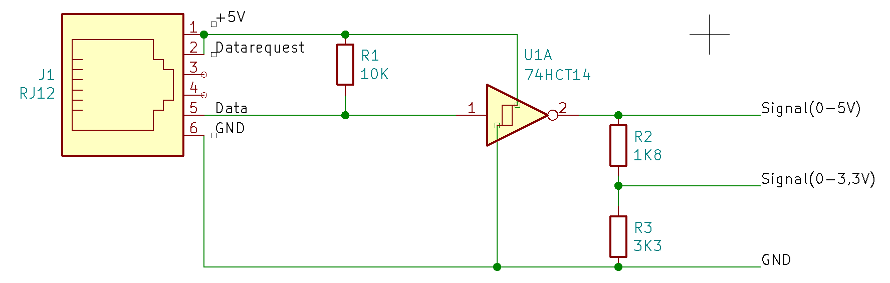
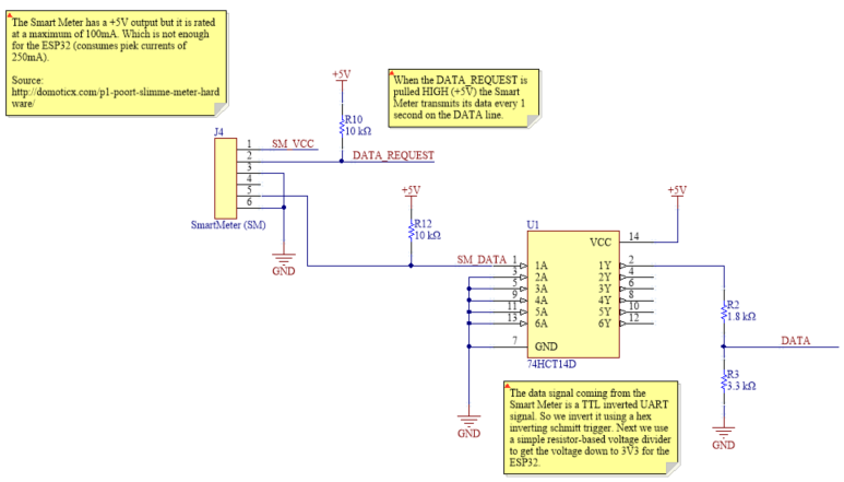
Here we run into our first problem. Due to the use of opto couplers, the "Data" (pin 5) line must be designed as an Open Collector output and must be logically inverted before it can be used with IoT device ( Raspberry Pi, ESP32, Arduino, ...).
A "Data" line LOW has a voltage of 0,2 V (0 - 1V), HIGH has a voltage of 5,0V with a maximum current of 30 mA.
The solution is either to use a pre-made cable like for instance this one (opens new window), or to provide the signal inversion yourself.
# Communication protocol
Here we run into our second problem. The P1 communication protocol of a Fluvius Smart Meter is based on the DSMR 5 standard used in the Netherlands but extended with the e-Mucs specifications. Therefore all solutions found on the internet for the Netherlands are not applicable for the Fluvius Smart Meter.
# Transfert speed and character formatting
The interface must use a fixed transfer speed of 115200 baud.
:: tip Note Due to the 115200 baud-rate the max. cable length for this serial communication is 2,5 m. :::
The Fluvius Smart Meter sends its data to the connected IoT device every single second and the transmission of the entire P1 telegram is completed within 1s.
The format of transmitted data is defined as “8N1”. Namely:
- 1 start bit,
- 8 data bits,
- no parity bit and
- 1 stop bit.
# Data readout
The Fluvius Smart Meter transmits the data message, as described below, immediately following the activation through the Request signal.

# End of transmission
The data transmission is complete after the data message has been transmitted. An acknowledgement signal is not provided for.
# Data objects
For more information on the OBIS codes see the DSMR 5 standard and e-Mucs specification.
# Electricity data
| OBIS reference | Value | Example |
|---|---|---|
| 0-0:96.1.1.255 | Equipment identifier | 0-0:96.1.1(4B384547303034303436333935353037) |
| 1-0:1.8.1.255 | Meter Reading electricity consumption (normal tariff) in 0,001 kWh | 1-0:1.8.1(123456.789*kWh) |
| 1-0:1.8.2.255 | Meter Reading electricity consumption (low tariff) in 0,001 kWh | 1-0:1.8.2(123456.789*kWh) |
| 1-0:2.8.1.255 | Meter Reading electricity injected (normal tariff) in 0,001 kWh | 1-0:2.8.1(123456.789*kWh) |
| 1-0:2.8.2.255 | Meter Reading electricity injected (low tariff) in 0,001 kWh | 1-0:2.8.2(123456.789*kWh) |
| 0-0:96.14.0.255 | Tariff indicator electricity. (1=normal, 2=low) | 0-0:96.14.0(0002) |
| 1-0:1.7.0.255 | Actual electricity power consumption in 1 Watt resolution | 1-0:1.7.0(01.193*kW) |
| 1-0:2.7.0.255 | Actual electricity power injected in 1 Watt resolution | 1-0:2.7.0(00.000*kW) |
| 0-0:96.7.21.255 | Number of power failures in any phases | 0-0:96.7.21(00004) |
| 0-0:96.7. 9.255 | Number of long power failures in any phases | 0-0:96.7.9(00002) |
| 1-0:99:97.0.255 | Power failure event log | 1-0:99.97.0(2)(0-0:96.7.19)(101208152415W)(0000000240s)(101208151004W)(0000000301s) |
| 1-0:32.32.0.255 | Number of voltage sags in phase L1 | 1-0:32.32.0(00002) |
| 1-0:52.32.0.255 | Number of voltage sags in phase L2 | 1-0:52.32.0(00001) |
| 1-0:72.32.0.255 | Number of voltage sags in phase L3 | 1-0:72.32.0(00000) |
| 1-0:32.36.0.255 | Number of voltage swells in phase L1 | 1-0:32.36.0(00000) |
| 1-0:52.36.0.255 | Number of voltage swells in phase L2 | 1-0:52.36.0(00003) |
| 1-0:72.36.0.255 | Number of voltage swells in phase L3 | 1-0:72.36.0(00000) |
| 1-0:32.7.0.255 | Instantaneous voltage L1 | 1-0:32.7.0(220.1*V) |
| 1-0:52.7.0.255 | Instantaneous voltage L2 | 1-0:52.7.0(220.2*V) |
| 1-0:72.7.0.255 | Instantaneous voltage L3 | 1-0:72.7.0(220.3*V) |
| 1-0:31.7.0.255 | Instantaneous current L1 | 1-0:31.7.0(001*A) |
| 1-0:51.7.0.255 | Instantaneous current L2 | 1-0:51.7.0(002*A) |
| 1-0:71.7.0.255 | Instantaneous current L3 | 1-0:71.7.0(003*A) |
| 1-0:21.7.0.255 | Instantaneous active power consumption L1 | 1-0:21.7.0(01.111*kW) |
| 1-0:41.7.0.255 | Instantaneous active power consumption L2 | 1-0:41.7.0(02.222*kW) |
| 1-0:61.7.0.255 | Instantaneous active power consumption L3 | 1-0:61.7.0(03.333*kW) |
| 1-0:22.7.0.255 | Instantaneous active power injected L1 | 1-0:22.7.0(04.444*kW) |
| 1-0:42.7.0.255 | Instantaneous active power injected L2 | 1-0:42.7.0(05.555*kW) |
| 1-0:62.7.0.255 | Instantaneous active power injected L3 | 1-0:62.7.0(06.666*kW) |
| 0-0:96.3.10.255 | Breaker state | 0-0:96.3.10(1) |
| 0-0:17.0.0.255 | Limiter treshold | 0-0:17.0.0(123.4*kW) |
| 1-0:31.4.0.255 | Fuse supervision threshold (L1) | 1-0:31.4.0(001*A) |
Warning
The Obis-references for High and Low tarif are switched for the Belgian meter compared to the Dutch meter!
# Messages
| OBIS reference | Value | Example |
|---|---|---|
| 0-0:96.1.4.255 | Version information | 0-0:96.1.4(50) |
| 0-0:96.13.0.255 | Text message max 1024 characters. | 0:96.13.0(303132333435363738393A3B3C3D3E3F3031) |
| 0-0:96.13.1.255 | Consumer message code | 0-0:96.13.1(3031203631203831) |
# Gas data
| OBIS reference | Value | Example |
|---|---|---|
| 0-n:24.1.0.255 | Device-Type | 0-1:24.1.0(003) |
| 0-n:96.1.0.255 | Equipment identifier | 0-1:96.1.0(3232323241424344313233343536373839) |
| 0-n:24.2.1.255 | Last 5-minute value (temperature converted), gas delivered to client in m3, including decimal values and capture time | 0-1:24.2.1(101209112500W)(12785.123*m3) |
| 0-n:96.1.1.255 | M-Bus Device ID 2 | 0-1:96.1.1(3232323241424344313233343536373839) |
| 0-n:24.4.0.255 | Valve state | 0-1:24.4.0(1) |
| 0-n:24.2.3.255 | Last value of ‘not temperature corrected’ gas volume in m³, including decimal values and capture time | 0-1:24.2.3(101209112500W)(12785.123*m3) |
# Thermal data
| OBIS reference | Value | Example |
|---|---|---|
| 0-n:24.1.0.255 | Device-Type | 0-1:24.1.0(003) |
| 0-n:96.1.0.255 | Equipment identifier | 0-1:96.1.0(3232323241424344313233343536373839) |
| 0-n:24.2.1.255 | Last 5-minute Meter reading Heat or Cold in 0,01 GJ and capture time | 0-1:24.2.1(12.34*GJ) |
# Water data
| OBIS reference | Value | Example |
|---|---|---|
| 0-n:24.1.0.255 | Device-Type | 0-1:24.1.0(003) |
| 0-n:96.1.0.255 | Equipment identifier | 0-1:96.1.0(3232323241424344313233343536373839) |
| 0-n:24.2.1.255 | Last 5-minute Meter reading in 0,001m3 and capture time | 0-1:24.2.1(12785.123*m3) |
Warning
Be aware of the fact that the number of OBIS codes and the order of them is not fixed. Therefore the connected IoT device must be able to interpret the P1 telegram.
# Development of the hardware
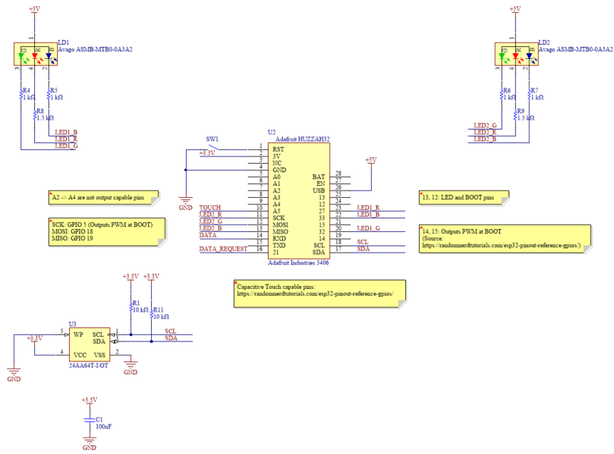
You can download the circuit, pcb and gerber files here (opens new window).
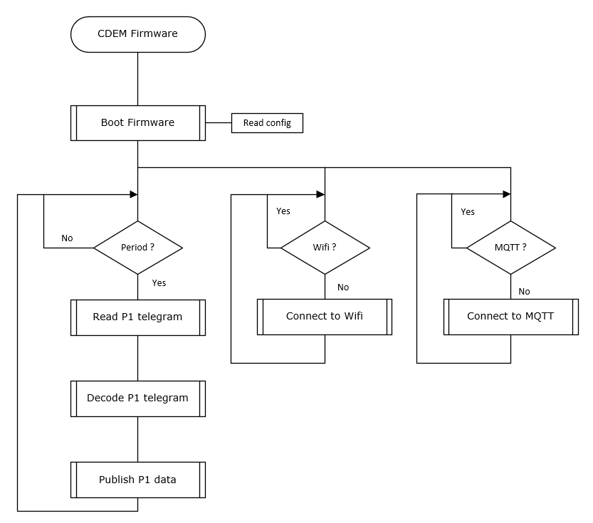
# Development of the firmware
This flowchart explains the program structure of the firmware.