# Required Hardware
This chapter contains a listing of all the components and tools required to build your very own Connected Digital Energy Meter device.

# CDEM Device Parts
The following sections give a detailed overview of all the parts that will be required to create a CDEM device.
# PCB Components
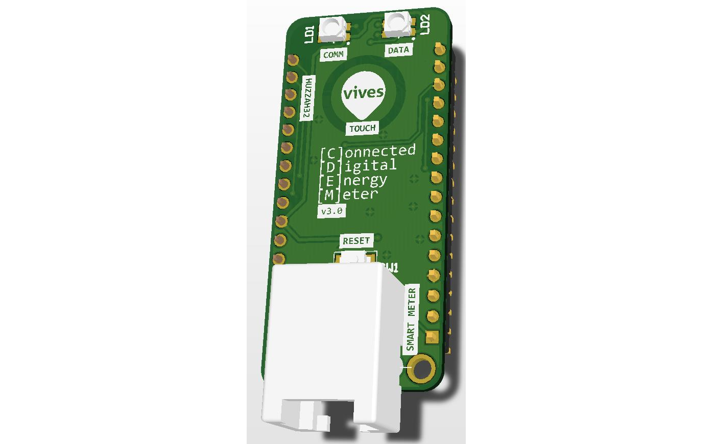
The table below provides an overview of the components required for the CDEM shield for the ESP32 Huzzah32.
| Description | Part | PCB Designator | Quantity | Farnell Order Code | Key Properties |
|---|---|---|---|---|---|
| Hex Inverter | 74HCT14D | U1 | 1 | 1201304 (opens new window) | 14 Pins SOIC |
| RJ11 Connector | 54601-906WPLF | J4 | 1 | 2135977 (opens new window) | Right Angle, Through Hole |
| 1k8 Resistor | MCWR08X1801FTL | R2 | 1 | 2447595 (opens new window) | SMD 0805 |
| 3k3 Resistor | ASC0805-3K3FT5 | R3 | 1 | 2078957 (opens new window) | SMD 0805 |
| 10k Resistor | CR0805-FX-1002ELF | R1, R10 - R12 | 3 | 1612522 (opens new window) | SMD 0805 |
| 1k5 Resistor | CRG0805F1K5 | R8, R9 | 2 | 3399596 (opens new window) | SMD 0805 |
| 1k Resistor | RK73H2ATTD1001F | R4 - R7 | 4 | 3548772 (opens new window) | SMD 0805 |
| RGB LED | ASMB-MTB0-0A3A2 | LD1, LD2 | 2 | 2401105 (opens new window) | SMD, PLCC-4 |
| Tactile Switch | B3U-1000P | SW1 | 1 | 1333652 (opens new window) | SMD, SPST-NO |
| 12 Pin Header | 22-28-4120 | U2 | 1 | 3049539 (opens new window) | Male, 2.54 mm Pitch, 1 Rows, 12 Contacts, Through Hole Straight |
| 16 Pin Header | 22-28-4161 | U2 | 1 | 3049545 (opens new window) | Male, 2.54 mm Pitch, 1 Rows, 16 Contacts, Through Hole Straight |
Datasheets
While Farnell only allow SME's to order components, the part numbers are provided so you can easily look for alternatives. Make sure to consult the datasheets of the components when selecting alternative components. While resistors and such are not that critical, the pinouts of the connectors and IC's are. Also make sure to take the key properties into account. We can recommend Gotron (opens new window) and Conrad (opens new window).
# Microcontroller
The brains of the Connected Digital Energy Meter system is the Adafruit HUZZAH32 – ESP32 Feather Board (opens new window), a cheap but versatile and widely supported microcontroller module.
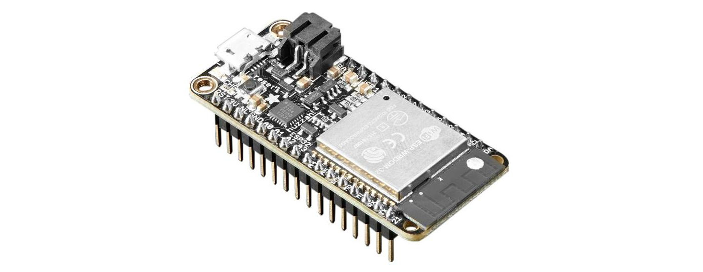
While it can be directly ordered from Adafruit (opens new window), other distributors are also available. Just have your pick:
- Antratek - HUZZAH32 – ESP32 Feather Board (opens new window)
- Kiwi Electronics - HUZZAH32 – ESP32 Feather Board (opens new window)
- Digi-Key Electronics - HUZZAH32 – ESP32 Feather Board (opens new window)
🔎 Huzzah32
When selecting another distributor make sure to select the exact same module as documented here. Other modules exists that are very similar but not compatible.
# Power Supply
As a power supply you can use any 5V USB micro power adapter you have laying around from an old phone or Raspberry PI. Just make sure that the power adapter is rated for at least 500mA and it has a USB micro connector.
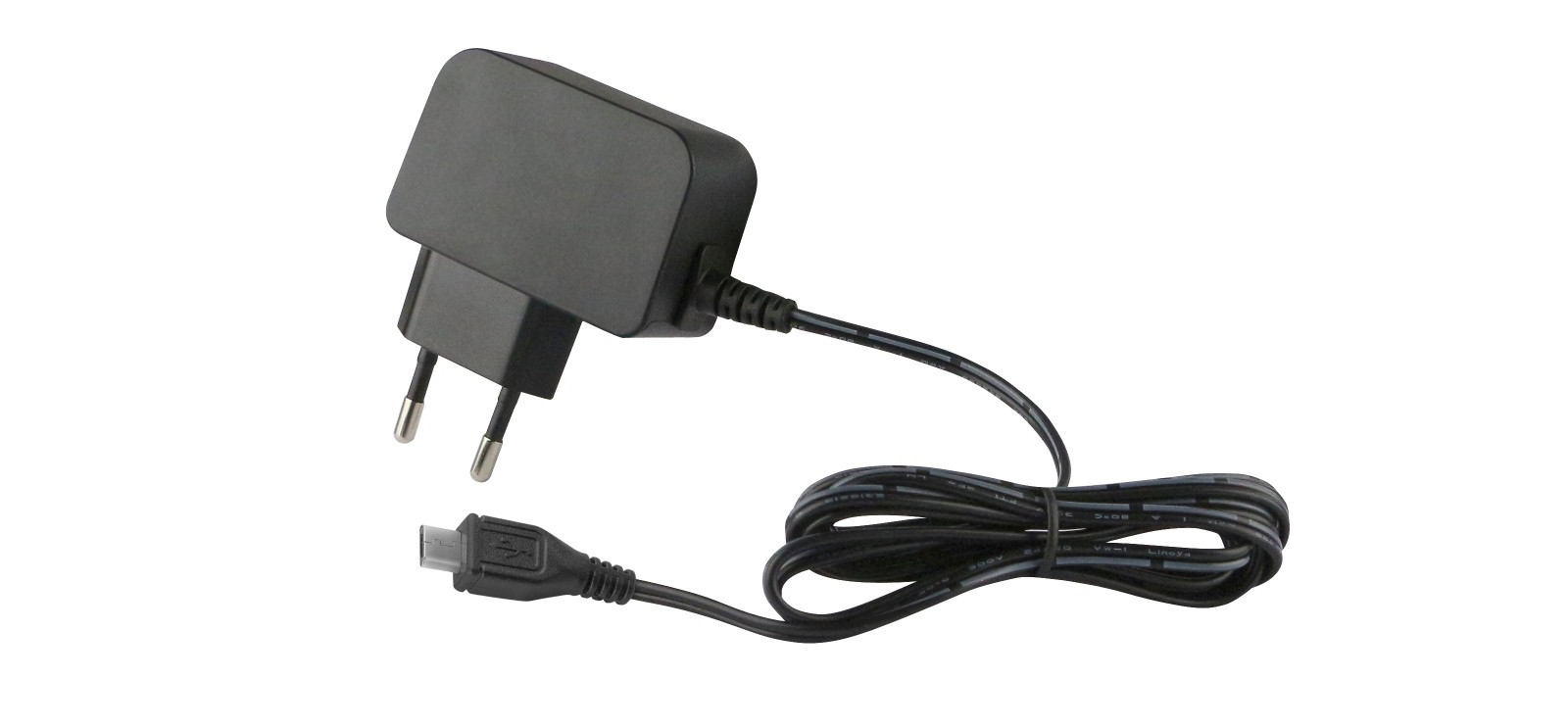
Most web-shops have a cheap power supply adapter available:
- Antratek - 5V USB Micro Power Adapter (opens new window)
- Kiwi Electronics - 5V USB Micro Power Adapter (opens new window)
- Digi-Key Electronics - 5V USB Micro Power Adapter (opens new window)
# Connecting to the Digital Meter
Connecting the Connected Digital Energy Meter to the Fluvius Digital meter requires an RJ11 cable with 4 internal wires. These are typically used for telephone connections, so chances are you may have one lying around.
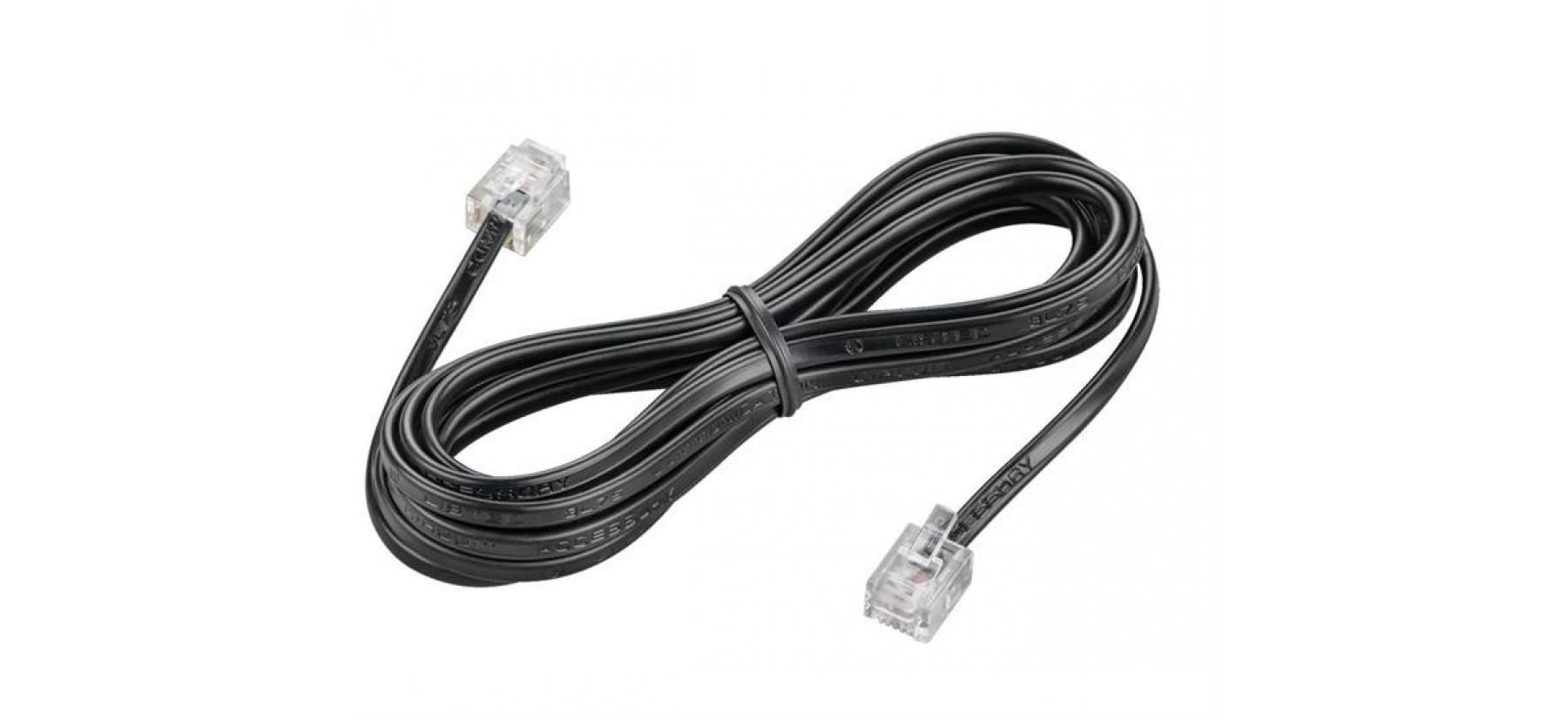
When ordering cables one of the cheapest distributors with the wides range of products is AlleKabels (opens new window). A length of 0.5 meter is more than enough.
🕵️ Check Connections
Make sure that the RJ11 cable has 4 or 6 wires (actually RJ12, which is also usable) and that both sides have the wires in the same order.
# Soldering Tools
To assemble the PCB shield, some basic soldering tools are required.
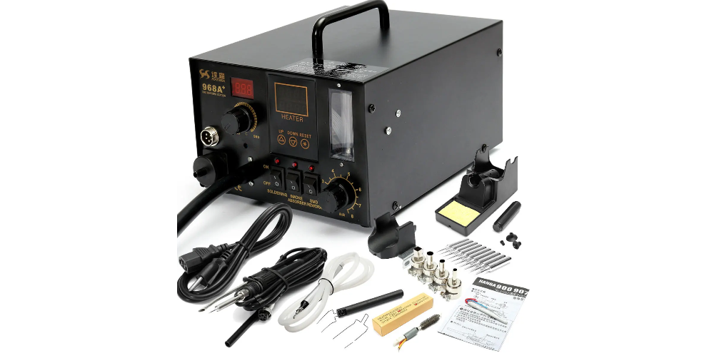
To solder the PCB you will need either a hot air soldering station and some soldering paste
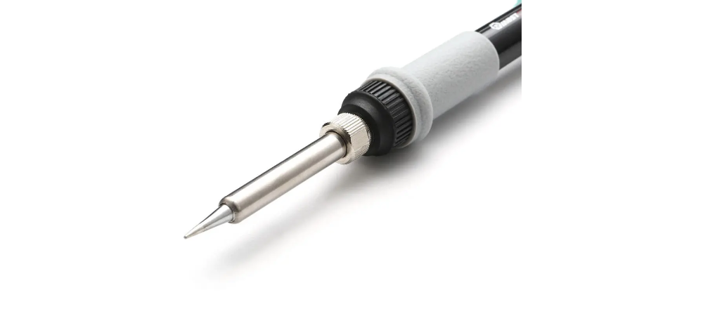
or a soldering iron with a small tip and thin soldering tin (0.5mm - 0.7mm).
A pair of tweezers to hold and place the SMD components.

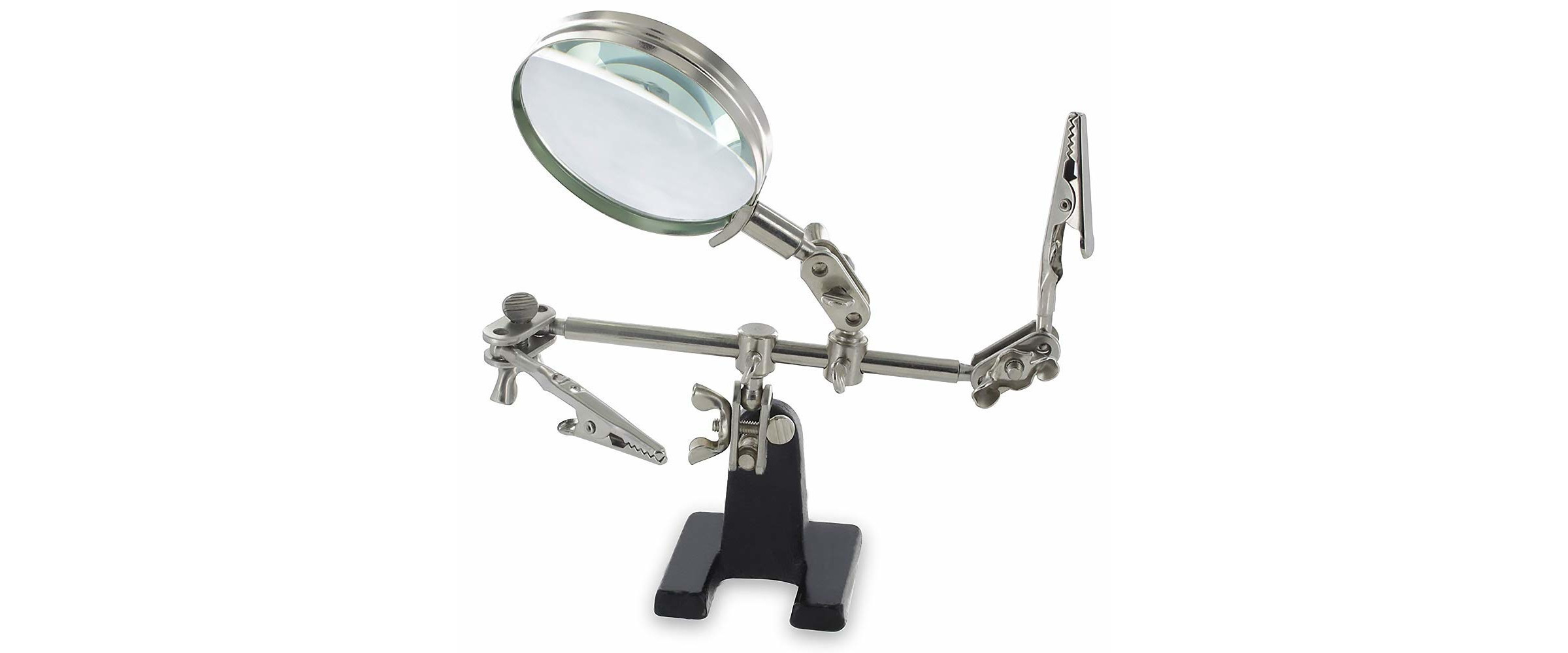
And optionally a magnifying glass to check on the placement of the components or possible short circuits.
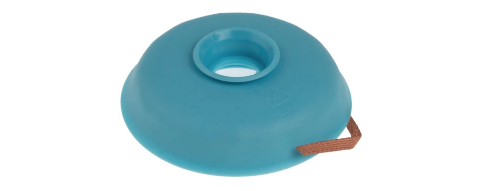
If you made a mistake it may be required to have some desoldering braid at hand too. This will allow you to cleanup some excessive tin.
← Introduction Assembly →
